project
January 31, 2022
11 min read
484 views
Automated Chessboard
Electromagnet chessboard with sensor grid and AI chess engine.

<h2>Project Overview</h2>
<p>Electromagnet chessboard with sensor grid and AI chess engine.</p>
<h2>Bill of Materials (BOM)</h2>
<ul>
<li>A microcontroller (Arduino or Raspberry Pi)</li>
<li>a grid of reed switches or hall effect sensors to detect piece locations</li>
<li>an electromagnet mounted on a 2-axis gantry system to move pieces</li>
<li>and a chess engine for AI.</li>
</ul>
<h2>Circuit Diagram & Component Arrangement</h2>
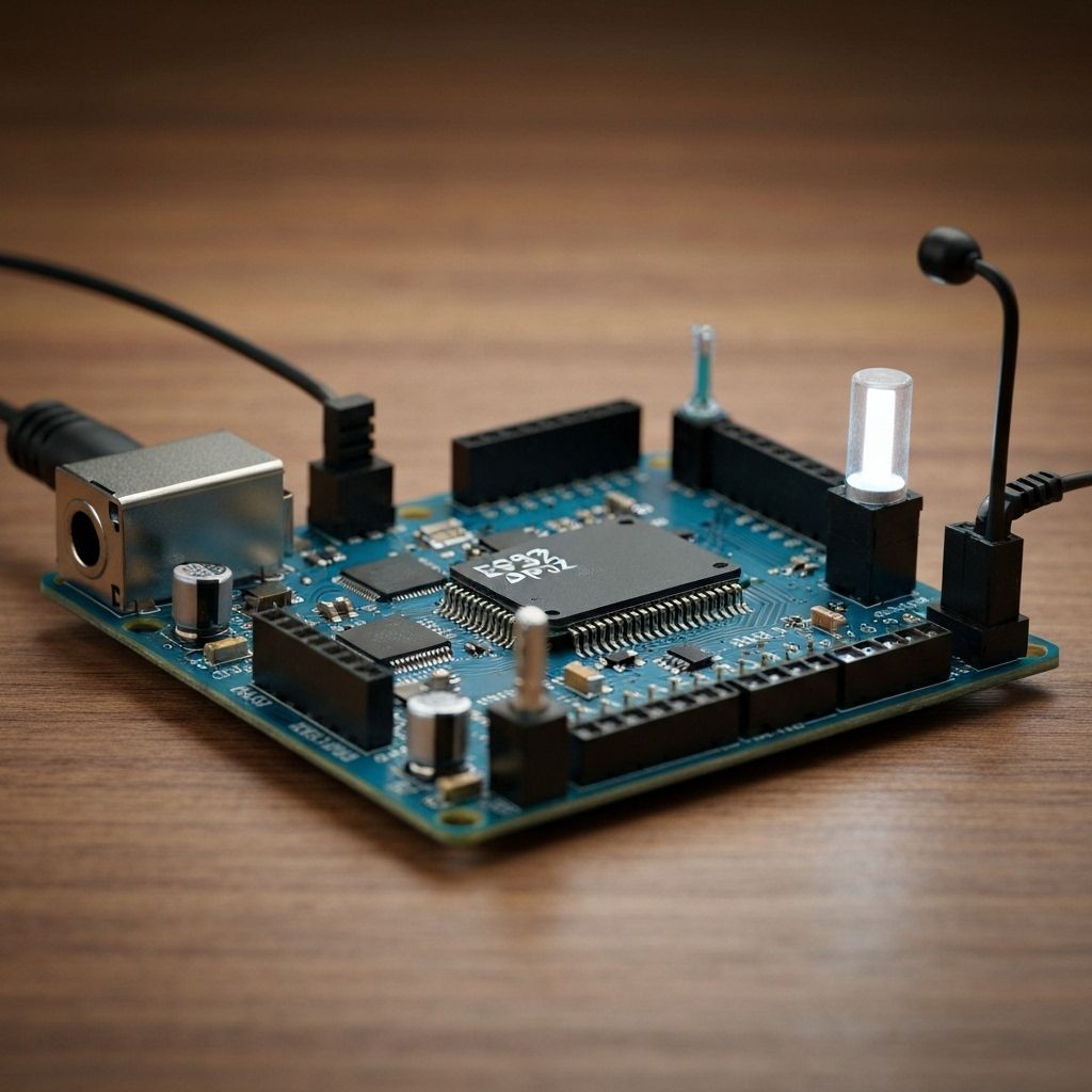
<p>Follow the wiring diagram below. Each component connects to specific pins on the microcontroller. Use a breadboard for prototyping and ensure all connections are secure before powering on.</p>
<p><strong>Wiring Summary:</strong> The sensor grid is multiplexed and read by the microcontroller to determine the board state. The microcontroller controls stepper motors for the X-Y gantry and an electromagnet to pick up and move the chess pieces based on moves from a chess engine.</p>
<h2>Step-by-Step Procedure</h2>
<ol>
<li><strong>Step 1 - Prepare Components:</strong> Gather all components from the BOM. Inspect for damage and verify ratings.</li>
<li><strong>Step 2 - Breadboard Layout:</strong> Place the microcontroller on the breadboard. Arrange components for clear wiring paths.</li>
<li><strong>Step 3 - Power Connections:</strong> Connect VCC and GND first. Ensure proper polarity for polarized components.</li>
<li><strong>Step 4 - Signal Wiring:</strong> Connect sensors and actuators per the wiring table. Double-check pin assignments.</li>
<li><strong>Step 5 - Upload Code:</strong> Connect USB, load the sketch, and upload. Verify serial output if applicable.</li>
<li><strong>Step 6 - Test & Calibrate:</strong> Power on and test each function. Calibrate sensors if needed.</li>
<li><strong>Step 7 - Enclosure (Optional):</strong> Mount in a 3D-printed or custom enclosure for durability.</li>
</ol>
<h2>Safety Notes</h2>
<ul>
<li>Always disconnect power before making wiring changes.</li>
<li>Use appropriate eye protection when soldering.</li>
<li>Adult supervision is required for makers under 16.</li>
<li>Do not exceed voltage ratings of components.</li>
</ul>

Manish Bookreader
Electronics enthusiast, Embedded Systems Expert, Linux/Networking programmer, and Software Engineer passionate about AI, electronics, books, and cooking.